Display 10 of 20
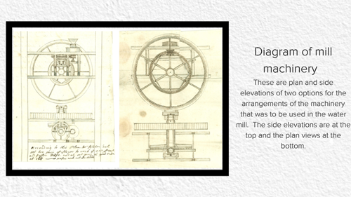
Diagram of mill machinery (Courtesy Badminton Estate D2700 QP4/5/2)
These are plan and side elevations of two options for the arrangements of the machinery that was to be used in the water mill. The side elevations are at the top and the plan views at the bottom. In both drawings the large circular wheel is the pit-wheel rather than the actual water wheel and the drawings show two different possible arrangements for the drive train and the grinding stones. The left hand drawing shows an offset grinding stone (with the triangular grain hopper being visible) while the drawing on the right side shows the grinding stones set directly above the wheel shaft. There are many variations of mill machinery but typically, as a waterwheel rotated the motion was transmitted through the wheel-shaft to the ‘pit-wheel’, which was the first gear wheel and set inside the mill. This drove a smaller bevelled ‘wallower’ which in turn drove the ‘spur wheel’ which turned a ‘lay shaft’. As the lay shaft rotated a ‘crown wheel’ or ‘drive wheel’ turned a ‘stone nut’ which rotated the runner stone (the upper millstone). A typical waterwheel rotated at about 10 revolutions per minute (r.p.m.) but by the time this had passed through all the gears, the speed of revolution had increased so that the runner-stone rotated at about 120 r.p.m.
Last reviewed: